Showing posts with label Technology. Show all posts
Ping is a valuable tool for troubleshooting all sorts of network or Internet problems. A ping command sends packets of information to devices on a network or the Internet to find out if they are available for connection. In Windows 7,8,10 the error message "Ping: Transmit Failed. General Failure" appears if the computer doesn't have the proper Internet protocol selected. You may select TCP/IPv4 or TCP/IPv6 in the control panel of your computer.


Solution 01: Disable all IPv4 or IPv6 transition technologies

In order to fix the issue, users are suggesting to disable Pv4 or IPv6 transition technologies. Please follow the next steps in order to disable them:
  • Go to Start Menu -> Enter cmd in the Search box.
  • Right-click on it -> Press on the Run as administrator.
  • Into the Command Prompt run the following commands :
    • netsh int ipv6 isatap set state disabled
    • netsh int ipv6 6to4 set state disabled
    • netsh interface teredo set state disable
  • After running these commands, close Command Prompt and restart your computer. Check to see if the problem is fixed and if you can run properly ping commands.

Solution 02: Reset your computer’s TCP/IP

If getting Ping general failure error, we can try resetting the TCP/IP and Winsock catalog:
  • Start Command Prompt as administrator. We showed you how to do that in the previous solution.
  • Into the Command Prompt run the following commands :
    • netsh i i r r
    • netsh winsock reset
  • After doing that, close Command Prompt and restart your computer.
After doing that, check if the problem is resolved.

Solution 03: Flush your computer’s DNS
 A solution that tons of users affected by this problem have found immensely effective in getting rid of it and restoring their computers’ ability to successfully run ping commands is flushing their computers’ DNS. Flushing your computer’s DNS is not only a pretty safe bet when it comes to fixing this problem but is also, in general, good for the health of your computer. To flush your computer’s DNS, you need to:
  1. Open the Start Menu.
  2. Search for “powershell“.
  3. Right-click on the search result titled Windows PowerShell and click on Run as administrator.
  4. One by one, type each of the following commands into the elevated instance of Windows PowerShell, pressing Enter after typing in each one:
ipconfig/release
ipconfig/renew
ipconfig /flushdns
netsh int ip reset c:\tcp.txt
netsh winsock reset 
  1. Close Windows PowerShell and restart your computer.
When the computer boots up, check to see whether or not the problem has been resolved.
 Solution 04: Reset your computer’s Hosts file

  1. Open a fresh instance of Notepad.
  2. Paste the following into the fresh instance of Notepad:
# Copyright (c) 1993-2006 Microsoft Corp.
#
# This is a sample HOSTS file used by Microsoft TCP/IP for Windows.
#
# This file contains the mappings of IP addresses to host names. Each
# entry should be kept on an individual line. The IP address should
# be placed in the first column followed by the corresponding host name.
# The IP address and the host name should be separated by at least one
# space.
# Additionally, comments (such as these) may be inserted on individual
# lines or following the machine name denoted by a ‘#’ symbol.
# For example:
#      102.54.94.97     rhino.acme.com          # source server
#       38.25.63.10     x.acme.com              # x client host
# localhost name resolution is handle within DNS itself.
#       127.0.0.1       localhost
#       ::1             localhost
  1. Press Ctrl + S to save the Notepad document.
  2. Name the Notepad document “hosts” (including the quotation marks), navigate to the directory you want the file to be saved in and click on OK.
  3. Press the Windows Logo key + R to open a Run dialog.
  4. Type the following into the Run dialog and press Enter:
%WinDir%\System32\Drivers\Etc
  1. Locate the hosts file, right-click on it, click on Rename, rename the file to old and press Enter.
  2. Move over the new “Hosts” file from wherever you saved it to, to %WinDir%\System32\Drivers\Etc.
  3. If you are asked to confirm the action while moving the file, do so.
Once the file has been moved, restart your computer and check to see if the problem has been resolved once it boots up.

Solution 5: Enable all of the ICMPv4-In rules in your computer’s Firewall settings

  1. Open the Start Menu.
  2. Search for “firewall“.
  3. Click on the search result titled Windows Firewall with Advanced Security.
  4. In the left pane of the window, click on Inbound Rules.
  5. In the right pane, locate every single Inbound Rule titled File and Printer Sharing (Echo Request – ICMPv4-In), right-click on it and click on Enable Rule.
  6. Once done, restart your computer.
  7. When the computer boots up, check to see if the issue has been fixed.


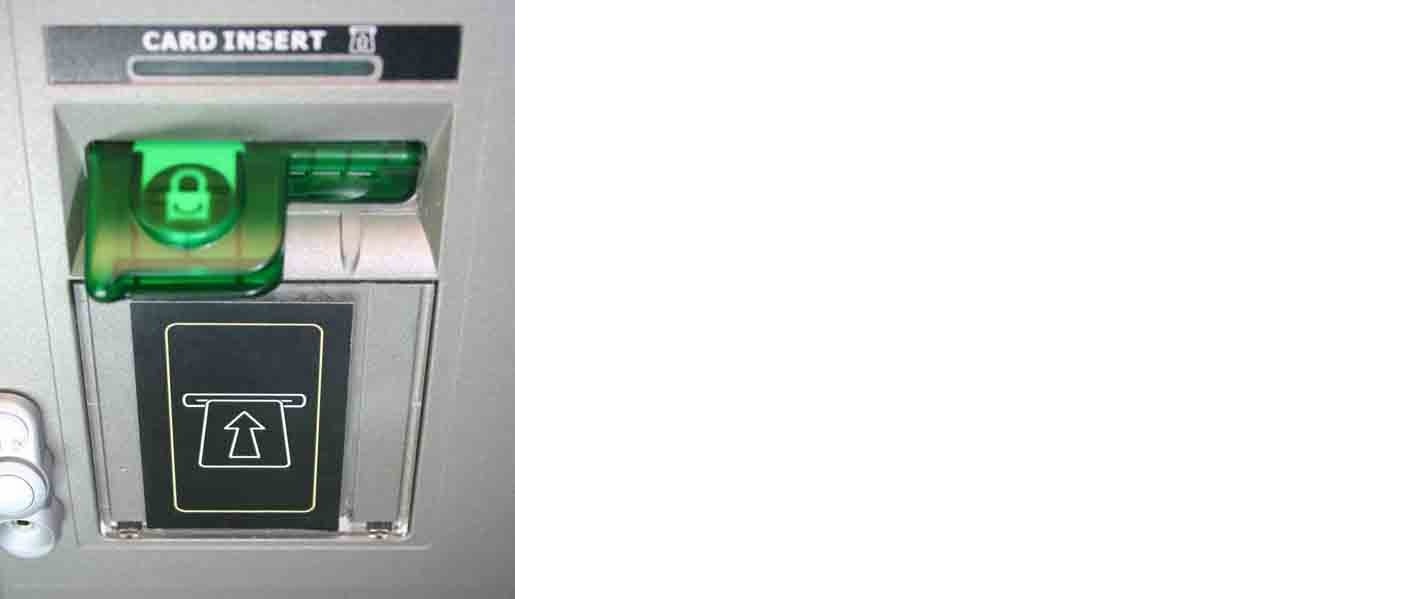
The Fraudulent Device Inhibitor is placed in front of
the entrance to the ATM card reader and is
specifically designed so that it is virtually impossible
for an ATM customer to enter his or her card into the
machine if a trapping device has been added to the
card reader.
The FDI has a number of unique features, including
a hologram built into the design that makes it more
difficult to replicate.

A skimming device would have to be bulky for it to be fitted over the FDI. The introduction of illumination behind the FDI also makes any attempt to attach a fraudulent device even more visible. An on-screen animated graphic with the message, ‘Does the card reader look like this?’ can also be used to heighten consumer awareness of what the card reader and the FDI should like.

Customer Awareness
The figure below shows how the FDI looks like when installed on the ATM. Also a
customer awareness message displayed on the ATM screen as the one below is highly
recommended

Customer Impact
Customer should be aware that the card
should be held from the right corner and
pushed into the card reader until the very end
as shown in the opposite picture.
The card should be pulled out of the card
reader the same way at the end of the
transaction.
Holding the card from the left side or not
pushing it to the very end (until it is pulled by
the card reader) may result on customers complaining that the ATM is not accepting their
card. Also failure to pull out the card from the card reader after the transaction
completion may result in card capture.

ENHANCED CARD DRIVE (JITTER)
This solution utilizes the superior control over card entry and return available with card
reader to cause a disrupted signal to be received by the skimming device (if installed).
The disrupted signal makes it much more difficult for criminals to make a copy of the
magnetic card information.

Customer Impact
When ECD is switched on customers will notice that the card vibrates slightly when
pushed in or out of the card reader. The amount of force that the card reader can exert to
push the card out of the reader is reduced. This is very unlikely to have any effect on the
cardholder unless their card is significantly bent in some way. In this case, the card may
take longer than normal to be pushed clear of the card reader. The timeout on the card
eject has to be increased to nine seconds to ensure that there is sufficient time for even
significantly bent cards to be correctly ejected from the reader.
Network Protocols In this chapter, you will find information on the history and working principles of several network protocols adopted in ATM network environment.

TCP/IP: TCP/IP is a protocol family created by the research group of National Defense in USA. Its purpose is to connect networks of different manufactures to one Internet for mutual access. Its success lies in that it provides some basic services (FTP, Email, HTTP, etc.) required by people on the network. People can use TCP/IP protocol to establish LAN, which can be connected with Internet via IP route. Considering the disaster recovery function required by the network on the battle field, US army designed it to be a powerful automatic disaster recovery system. This design permits big-scale network without too much management. However, this feature makes it impossible for the fault in a certain section of the network to be timely diagnosed, therefore it may stay in unavailable status for a long time.
Same as other network protocols, TCP/IP adopts a layer structure, as shown in Figure 4-1.


FIGURE 4-1: TCP/IP NETWORK LAYERS AND PROTOCOLS

 In TCP/IP protocol, different physical devices are labeled with IP addresses. The terminal application connects with the peer via SOCKET.

 
 FIGURE 4-2: SOCKET CONNECTION 

X.25: X.25 is a set of internationally recognized communication protocols defined by CCITT (now called ITU).
In the communication protocol standards defined by ITU,X series represents PSN (Packet Switching Network) protocol; V series represents PSTN (Public Switched Telephone Network) protocol; I series represents ISDN ( Integrated Services Digital Network) protocol.

X.25 protocol defines the interface with packet switching network at DTE (Data Terminal Equipment). DTE accesses X.25 network by connecting DCE (Data Communicational Equipment).Thus X.25 defines the interface between DTE and DCE. X.25 hasn't defined data transmission method in the packet switching network, which is fully accomplished by X.25 network.

One feature of X.25 is that it provides the reliable service, which means it ensures data is transmitted in sequence. This makes the application easy, for you do not need to consider errors in data transmission. On the other hand, it is just the reliable service that lowers the transmission performance (such as bandwidth and time), compared with those unreliable communication protocols that may discard the communication protocol of the data packet, such as Frame Relay.

 X.25 is a network layer protocol, which only transfers data packets to X.25 network in the mode accepted by X.25 network.

The data link layer protocol under X.25 protocol layer is the LAPB ( Link Access Procedure Balanced) protocol of HDLC (High-Level Data Link Control). The variation of HDLC protocol not only includes LAPB, but also includes SDLC of IBM.LAPB is a very reliable data link layer protocol, which enhances data error recovery.

X.25 is also a layered protocol, whose network layers are shown in Figure 4-3.


FIGURE 4-3: X.25 NETWORK LAYER 

  SNA (System Network Architecture) /SDLC (Synchronized Data Link Control)
 SNA is not a private product, but a network architecture for distributed processing of IBM. It defines a network easy to be established and modified. SNA supports the interconnection between different products with a set of standard network protocols. One important feature of SNA is the network data transmission is transparent to the terminal user or the terminal application.

As shown in Figure 4-4, the terminal user accesses SNA network via an LU (Logic Unit) port and a virtual link is established between LUs for data transmission.


 FIGURE 4-4: THE TERMINAL USER ACCESSES SNA NETWORK VIA LU

 For the terminal user, the connections between LUs seem to be the direct connection. In fact, data transmission between LUs is a complicated process. During the transmission, data must undergo the process of coding, routing and error tolerance before it can be sent to the peer correctly. To accomplish the complicated process, IBM defines a network layered structure:
 
FIGURE 4-5: SNA NETWORK LAYERS 

In the above network structure, layer 2 is data link layer and the data link layer protocol in SNA is SDLC protocol, which defines the link control function in data transmission. In fact, SDLC is variation of HDLC.
In SNA network, each physical node is labeled with PU. Since the node has different types, PU’s types also differ, which include PU-T1, PU-T2, PU-T4 and PU-T5.

 LU permits the end user to access SNA network resources and interact with other LU users. LU end users communicate via LU-LU protocol.

You can find many descriptions of LU-LU protocol, and deem LU-LU protocol a session. In SNA network, session refers to a temporary logic connection between two LU end users.

 The session only starts after two LU end users are bound. LU binding process is a complicated protocol command interactive sequence, which almost involves all layers of SNA network. The disconnection of the binding of two LUs is just reverse.

 LU is a general name. In fact, there are two kinds of LUs: PLU (master LU) and SLU (slave LU).Usually the Central has one PLU, which is responsible for responding the session establishment request from other LUs and then establishing the session. PLU is also responsible for error recovery. LU has several different forms of LU-T0, LU-T1, LU-T4, etc. 
Copyright © 2013 MEDIA INFO